
Advanced Pinball Lamp Controller
Data East Hardware Installation
1. Turn off power to the game and wait 10 minutes.
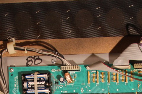
2. Remove the translite from the game and lower the speaker panel as shown.
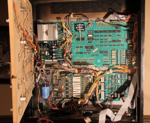
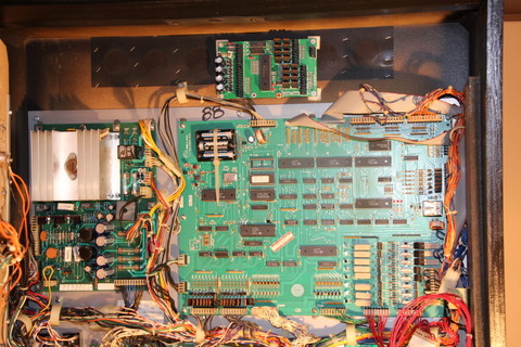
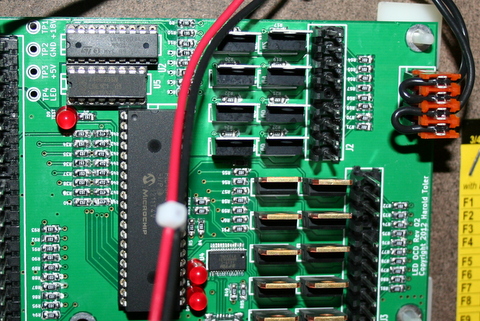
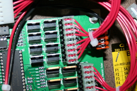
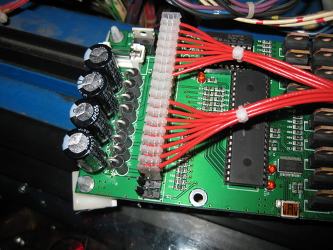
3. Choose a location for the LED OCD board. I recommend the open area near the top of the backbox as shown in the picture below.
4. Insert the four provided standoffs in the four corner holes in the PCB. You also have the option of installing the board using adhesive standoffs.
5. If you decide to use adhesive standoffs instead, clean the area where the standoffs will be stuck using isopropyl alcohol.
6. Install the PCB in the location you have chosen. Make sure to leave enough room beside the LED OCD board for the USB cable.
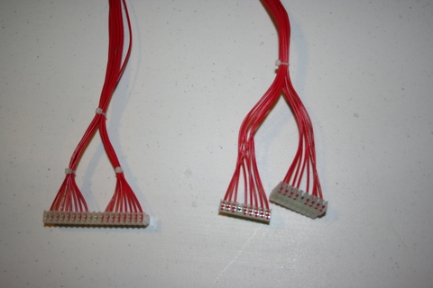
7. One end of the ground cable has a single 4-pin connector. The other has two 9-pin connectors.
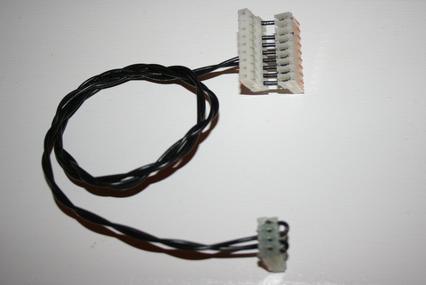
8. Connect the single 4-pin connector to J4 of the LED OCD board.
9. If there is a connector already connected to CN5 of the CPU board, remove it first.
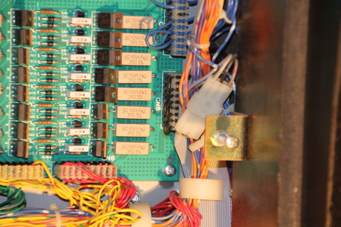
10. Connect one of the remaining connectors of the provided ground cable to CN5 of the CPU board.
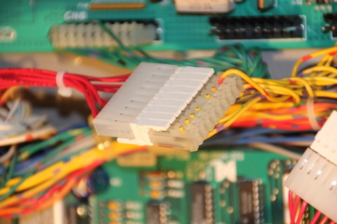
WARNING: Make sure that the side of the connector that hangs over the CPU board has the black cover installed. This prevents the legs of the resistors from being able to short to the inside of the connector.
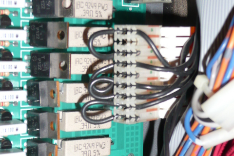
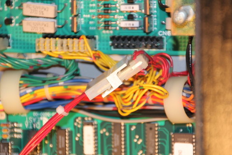
11. If you disconnected a connector from CN5, insert the provided 9-pin Z-connector in the remaining connector of the ground cable, then attach the connector you removed to the other side of the Z-connector.
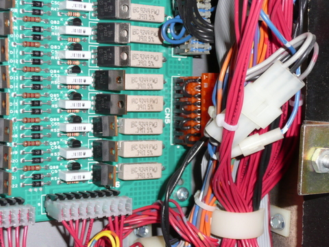
12. Secure the cable using any available cable clips.
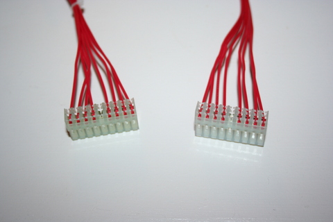
13. The row output cable can be identified by two connectors with keys at pin 4. One of them will be a 9-pin connector, and the other will be either 9-pin or 11-pin.
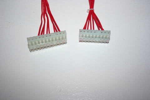
14. If your cable has an 11-pin connector, connect it to J3 of the LED OCD board. If it has two 9-pin connectors, connect either one to J3 of the LED OCD board. In this case, pins 10 and 11 of J3 will be exposed.
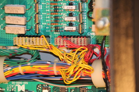
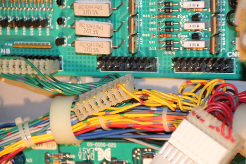
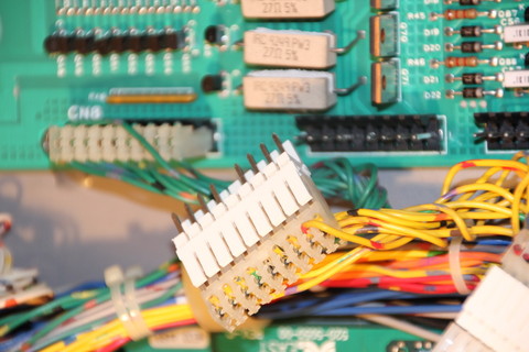
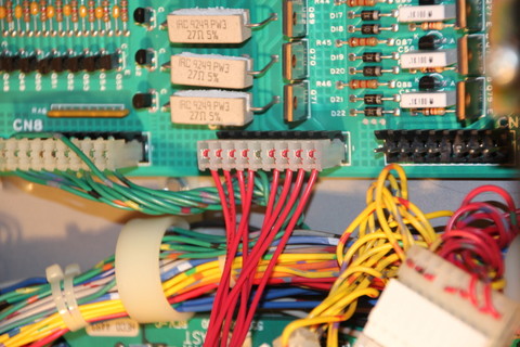
15. Disconnect the lamp matrix row connector, which is connected to CN6, from the CPU board.
16. Insert the provided 9-pin Z-connector into the connector removed from the CPU board.
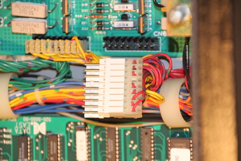
17. Insert the other side of the Z-connector into the 9-pin connector on the LED OCD row output cable.
18. Secure the cable using any available cable clips.
19. The column output cable can be identified by the two 9-pin (with keys at pin 5) connectors on opposite ends of the cable.
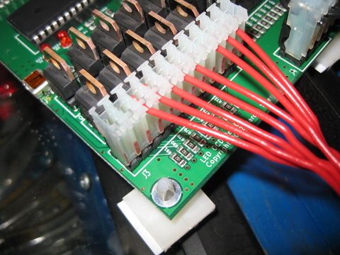
20. Connect either of the 9-pin connectors to J2 of the LED OCD board. Both are keyed, identically. Make sure the side of the connector with the ramp is pressing against the "springy" side of J2. This actually goes for all of the connectors, but this one can be flipped without noticing it since the key is in the center location. The wires should exit the connector over the top of J4.
21. Disconnect the lamp matrix column connector, which is connected to CN7, from the CPU board.
22. Insert the provided 9-pin Z-connector into the connector removed from the CPU board.
23. Insert the other side of the Z-connector into the remaining 9-pin connector on the LED OCD column output cable.
24. Secure the cable using any available cable clips.
25. The remaining cable is the row/column input cable, and can be identified by the 18-pin connector on one end.
26. Connect the 18-pin connector to J1 on the LED OCD board. Pins 19 and 20 of J1 will still be exposed. The connector is keyed to prevent it from being installed incorrectly.
27. On the other end of the input cable, there are two differently keyed 9-pin connectors. Connect the one with the key at pin 5 to CN7 of the CPU board.
28. Connect the other connector with the key at pin 4 to CN6 of the CPU board.
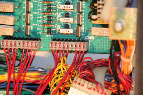
29. Secure the cable using any available cable clips.
30. You can now turn on the machine. Verify that D11 and D10 are lit solid. D9 should blink slowly (1 second on, 1 second off).
The insert lights should work, but they will be running at default settings and should be reconfigured for best results.
PC Software and USB Cable
You have the option of using PC Software and a mini-USB cable to change settings on the board.
1. Turn off power to the game and wait 10 minutes.
2. Connect the a mini-USB cable to the mini-USB connector J5 on the LED OCD board.
You are now ready for software installation.