
Advanced Pinball Lamp Controller
Stern SAM Hardware Installation
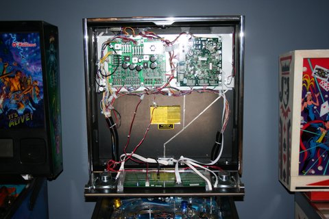
1. Turn off power to the game and wait 10 minutes.
2. Remove the translite from the game and lower the speaker panel as shown. The fluorescent lamp bulb is also removed in this picture. Removing the bulb is not necessary, but will make the rest of the installation easier.
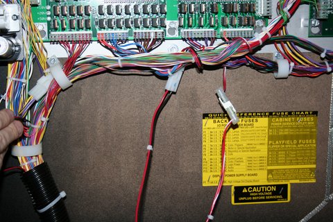
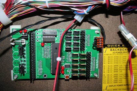
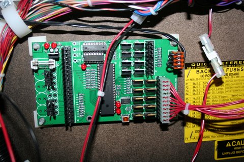
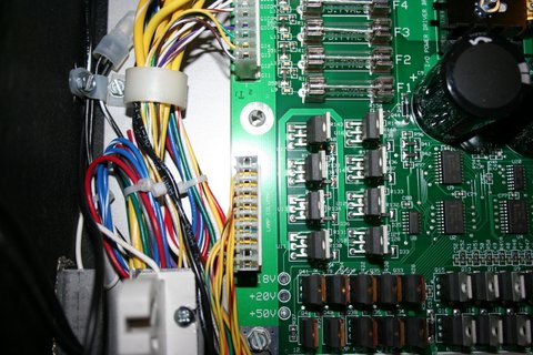
3. Choose a location for the LED OCD board. I recommend the open area as shown in the picture below.
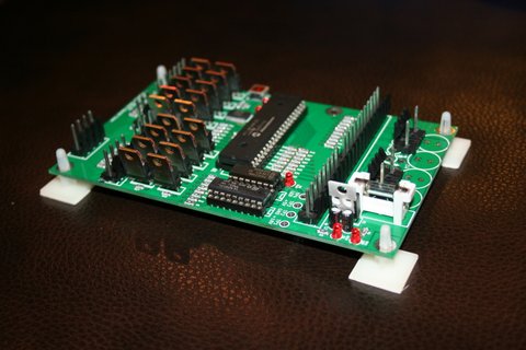
4. Insert the four provided standoffs in the four corner holes in the PCB. Since the back of the backbox is wood, you may decide to install the board using screws. The adhesive standoffs do seem to do a pretty good job, though.
5. Clean the area where the standoffs will be stuck using isopropyl alcohol. Sanding some of the paint spray first to get a nice smooth area to stick the standoffs also helps. Again, you have the option of using screws to mount the board if you want it more secure.
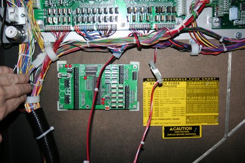
6. Remove the backing from the adhesive pads on the standoffs and place the PCB in the location you have chosen. Make sure to leave enough room on the side of the LED OCD board for the USB cable. In this mounting location, that's not really an issue.
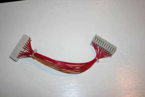
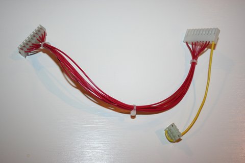
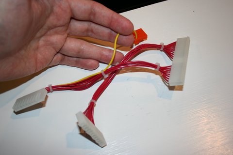
7. One end of the ground cable has a single 4-pin connector. The other has two 10-pin connectors.
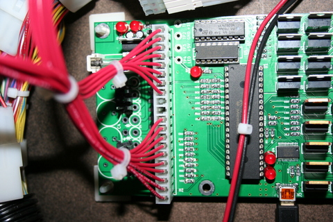
8. Connect the single 4-pin connector to J4 of the LED OCD board.
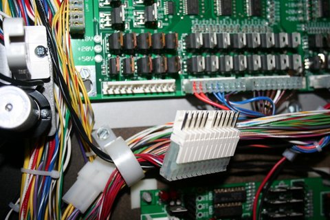
9. If there is a connector already connected to J10 of the SAM power driver board, remove it first.
10. Connect one of the remaining connectors of the provided ground cable to J10 of the SAM power driver board.
11. If you disconnected a connector from J10, insert the provided 10-pin Z-connector in the last connector of the ground cable, then attach the connector you removed from J10 to the other side of the Z-connector. There are two 10-pin Z-connectors, but only one is keyed properly to be used here.
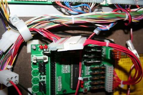
12. Secure the cable using any available cable clips.
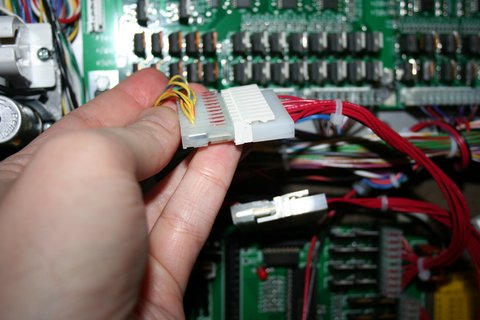
13. The row output cable can be identified by the 11-pin connector.
14. Connect the 11-pin connector to J3 of the LED OCD board.
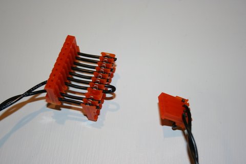
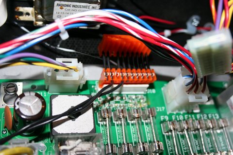
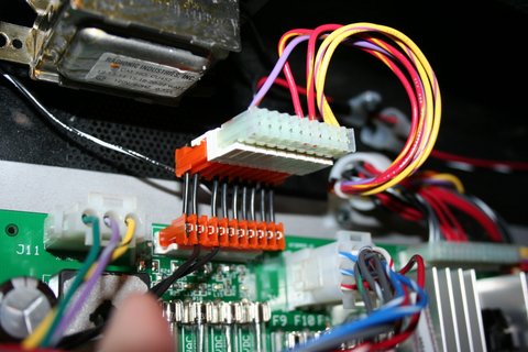
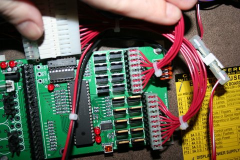
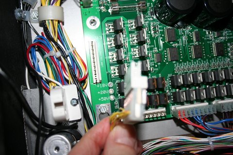
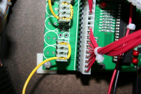
15. Disconnect the lamp matrix row connector from the power driver board. This includes the connector attached to J12 of the power driver board.
16. Insert the provided 12-pin Z-connector into the connector removed from the power driver board.
17. Insert the other side of the Z-connector into the 12-pin connector on the LED OCD row output cable.
18. Secure the cable using any available cable clips.
19. The column output cable can be identified by the 9-pin, 10-pin, and 4-pin connectors.
20. Connect the 9-pin connector to J2 of the LED OCD board. Make sure the side of the connector with the ramp is pressing against the "springy" side of J2. This actually goes for all of the connectors, but this one can be flipped without noticing it since the key is in the center location. The wires should exit the connector over the top of J4.
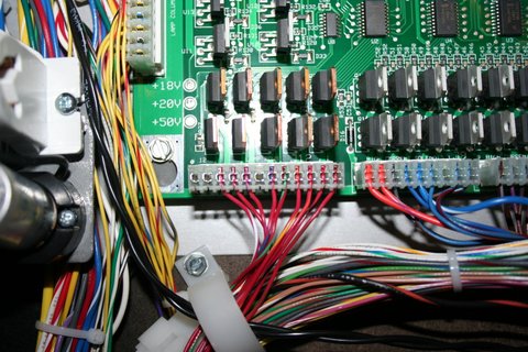
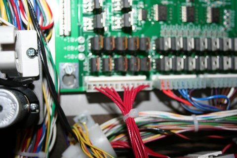
21. Disconnect the lamp matrix column connector from the power driver board. This includes the connector attached to J13 of the power driver board.
22. Insert provided 10-pin Z-connector into the connector removed from the power driver board.
23. Insert the other side of the Z-connector into the 10-pin connector on the LED OCD column output cable.
24. Connect the 4-pin connector of the column output cable to either of the 4-pin (two are keys) connectors on the LED OCD board.
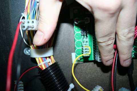
25. Secure the cable using any available cable clips.
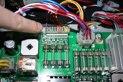
26. The remaining cable is the row/column input cable, and can be identified by the 20-pin connector on one end.
27. Connect the 20-pin connector to J1 on the LED OCD board.
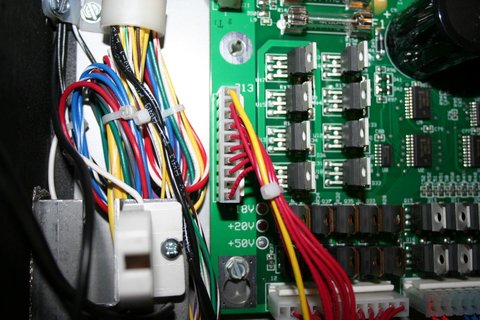
28. On the other end of the input cable, connect the 12-pin connector to J12 of the power driver board.
29. Connect the 10-pin connector to J13 of the power driver board.
30. Connect the 4-pin connector to the remaining 4-pin (two keys) connector on the LED OCD board.
31. Secure the cable using any available cable clips.
32. You can now turn on the machine. Verify that D11 and D10 are lit solid. D9 should blink slowly (1 second on, 1 second off).
The insert lights should work, but they will be running at default settings and should be reconfigured for best results.
PC Software and USB Cable
You have the option of using PC Software and a mini-USB cable to change settings on the board.
1. Turn off power to the game and wait 10 minutes.
2. Connect the a mini-USB cable to the mini-USB connector J5 on the LED OCD board.
You are now ready for software installation.