
Advanced Pinball Lamp Controller
Stern SAM Rev 3/4 Hardware Installation
1. Turn off power to the game and wait 10 minutes.
2. Remove the translite from the game and lower the speaker panel as shown. Removing the bulb is not necessary, but will make the rest of the installation easier.
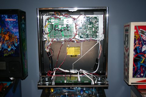
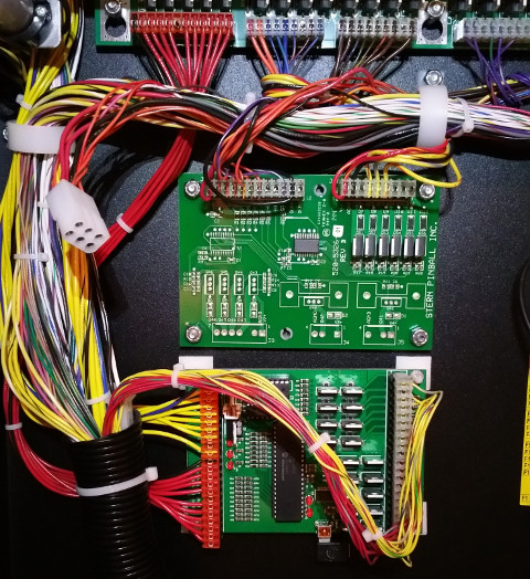
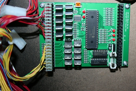
3. Choose a location for the LED OCD board. I recommend the open area as shown in the picture below.
4. Since the back of the backbox is wood for the older style backbox, you will normally install the board using screws. The self-retaining washers that are included can be used to hold the screw and standoff in place while installing. The newer, metal backbox, however, you will use the adhesive standoffs and a different mounting position.
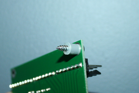
5. If you decide to use adhesive standoffs instead, clean the area where the standoffs will be stuck using isopropyl alcohol. Sanding some of the paint spray first to get a nice smooth area to stick the standoffs also helps.
6. Make sure to leave enough room on the side of the LED OCD board for the USB cable.
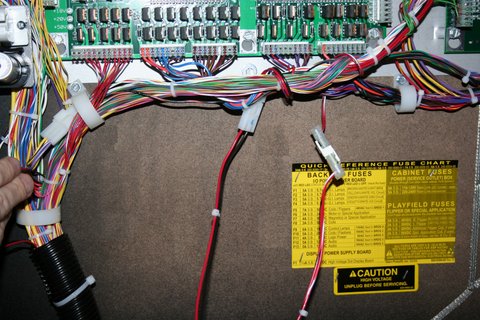
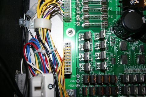
NOTE: The newest games (including Star Trek Pro, Iron Man VE, etc. have additional boards (shown outlined in the red boxes) attached between the power driver board and the playfield harness. The boards should be removed and stored in a safe place.
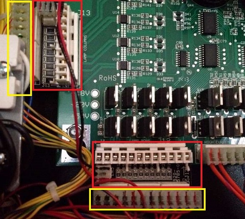
7. Disconnect the lamp matrix row connector from the power driver board. This includes the connector attached to J12 of the power driver board.
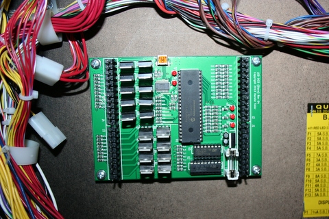
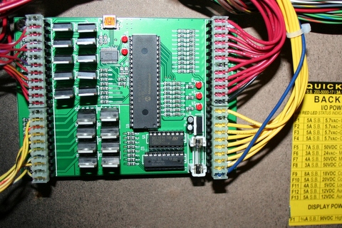
8. Connect the lamp matrix row connector that you just removed to J4 of the LED OCD board.
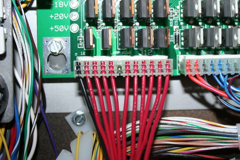
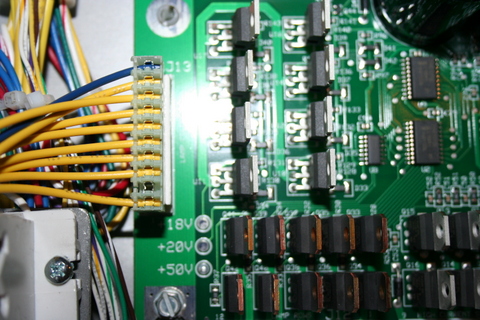
9. Disconnect the lamp matrix column connector from the power driver board. This includes the connector attached to J13 of the power driver board.
10. Connect the lamp matrix column connector that you just removed to J3 of the LED OCD board.
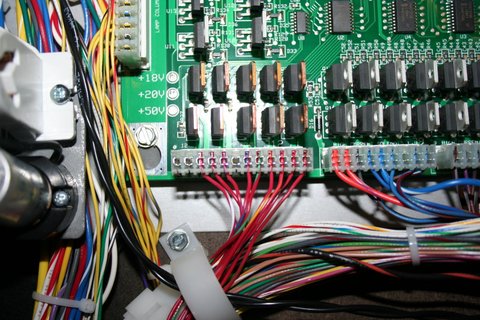
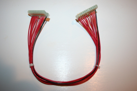
11. The row input cable is red and can be identified by the 12-pin connectors on both ends.
12. Connect one of the 12-pin connectors to J2 of the LED OCD board.
13. Connect the other 12-pin connector to J12 of the power driver board.
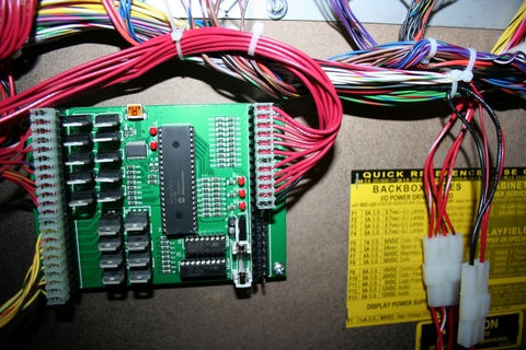
14. Secure the cable using any available cable clips.
15. The column input cable is yellow and can be identified by the 10-pin connectors on both ends.
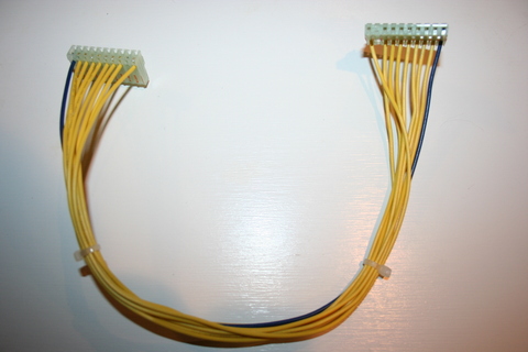
16. Connect one of the 10-pin connectors to J1 of the LED OCD board.
17. Connect the other 10-pin connector to J13 of the power driver board.
18. Secure the cable using any available cable clips.
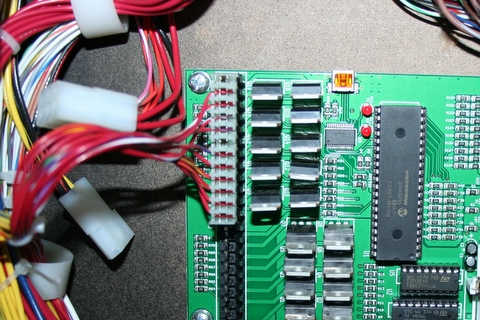
19. You can now turn on the machine. Verify that D11 and D10 are lit solid. D9 should blink slowly (1 second on, 1 second off).
The insert lights should work, but they will be running at default settings and should be reconfigured for best results.
PC Software and USB Cable
You have the option of using PC Software and a mini-USB cable to change settings on the board.
1. Turn off power to the game and wait 10 minutes.
2. Connect the a mini-USB cable to the mini-USB connector J5 on the LED OCD board.
You are now ready for software installation.