
Advanced Pinball Lamp Controller
Williams System 9 Hardware Installation
1. Turn off power to the game and wait 10 minutes.
2. Remove the translite from the game and lower the speaker panel as shown.
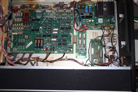
3. Choose a location for the LED OCD board. Different System 9 machines have open areas in different locations, so just choose an area that the board fits in and still allows the cables to reach.
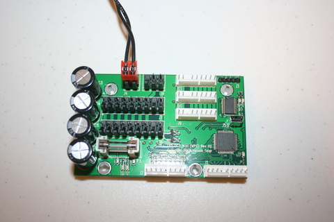
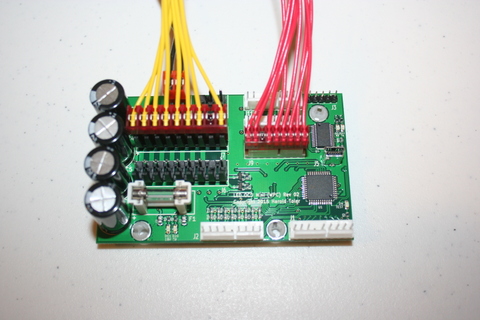
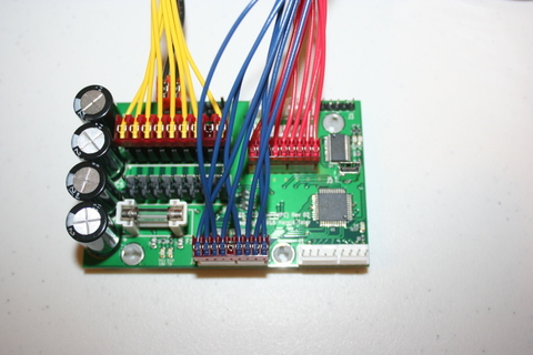
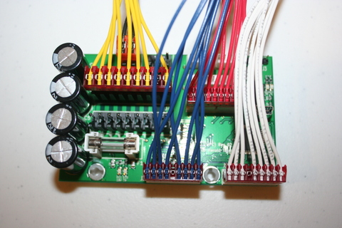
4. Use the included screws to install the PCB as shown.

5. One end of the ground (black) cable has a single 2-pin connector. The other has two 9-pin connectors.
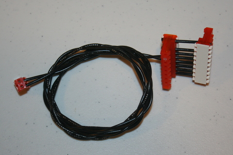
6. Connect the single 2-pin connector to J4 of the LED OCD board.
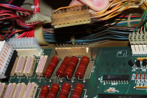
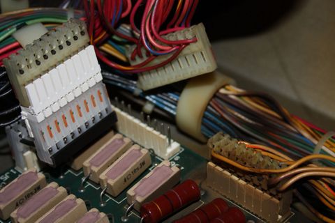
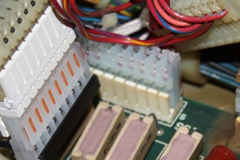
7. If there is a connector already connected to 1J5 of the CPU board, remove it first.
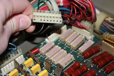
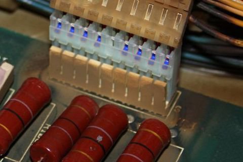
8. Connect one of the remaining connectors of the provided ground cable to 1J5 of the CPU board.
WARNING: Make sure that the side of the connector that hangs over the CPU board has the cover installed. This prevents the legs of the resistors from being able to short to the inside of the connector.

9. If you disconnected a connector from 1J5, insert the provided 9-pin Z-connector in the remaining connector of the ground cable, then attach the connector you removed to the other side of the Z-connector.
10. Secure the cable using any available cable clips.
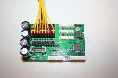
11. The column output (yellow) cable has two 9-pin connectors, one with a key at pin 5, the other with a key at pin 8.
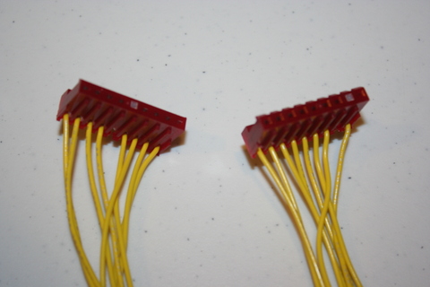
12. Connect the 9-pin connector with the key at 8 to J6 of the LED OCD board.
13. Disconnect the lamp matrix column connector, which is connected to 1J7, from the CPU board.
14. Insert the provided 9-pin Z-connector into the connector removed from the CPU board.
15. Insert the other side of the Z-connector into the remaining 9-pin connector on the LED OCD column output cable.

16. Secure the cable using any available cable clips.
17. The row output (red) cable has two 9-pin connectors, one bigger (0.156" pitch) than the other (0.100" pitch).
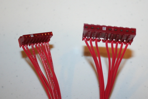
18. Connect the smaller connector to J9 of the LED OCD board.
19. Disconnect the lamp matrix row connector, which is connected to 1J6, from the CPU board.
20. Insert the provided 9-pin Z-connector into the connector removed from the CPU board.
21. Insert the other side of the Z-connector into the remaining 9-pin connector on the LED OCD row output cable.

22. Secure the cable using any available cable clips.
23. The column input (blue) cable has two 9-pin connectors, one bigger (0.156" pitch) than the other (0.100" pitch).
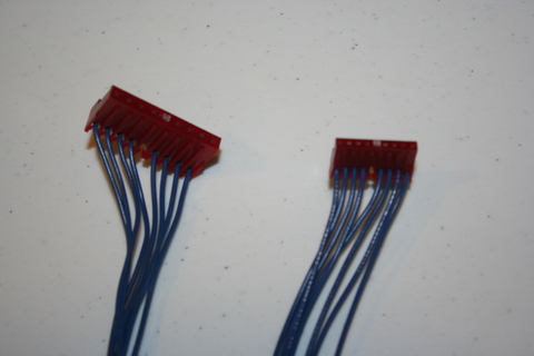
24. Connect the smaller connector to J2 of the LED OCD board.
25. Connect the bigger connector to 1J7 of the CPU board.
26. Secure the cable using any available cable clips.
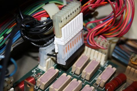
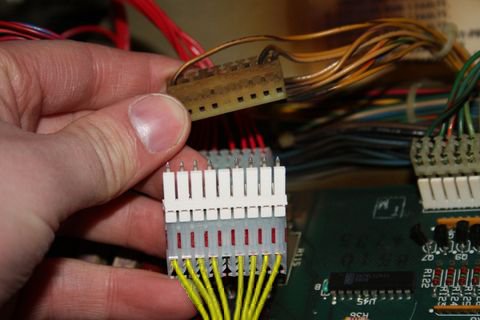
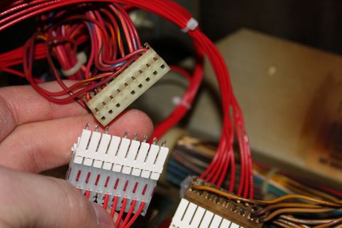
27. The row input (white) cable has two 9-pin connectors, one bigger (0.156" pitch) than the other (0.100" pitch).
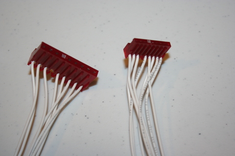
28. Connect the smaller connector to J1 of the LED OCD board.
29. Connect the bigger connector to 1J6 of the CPU board.
30. Secure the cable using any available cable clips.
31. Make sure you have replaced your controlled bulbs with LEDs. If you still have incandescent bulbs installed when you turn on the power, you will blow the fuse on the LED OCD board. A few incandescents are OK, but not a game full of them. If you really need to use a bunch of incandescent bulbs, you can increase the fuse to a 4A to make it work like the original LED OCD, but this will result in the LED OCD being in danger of damage if a short occurs.
32. You can now turn on the machine. Verify that D11 and D10 are lit solid. D9 should blink slowly (1 second on, 1 second off).
The insert lights should work, but they will be running at default settings and should be reconfigured for best results.
PC Software and USB Cable
You have the option of using PC Software and a mini-USB cable to change settings on the board.
1. Turn off power to the game and wait 10 minutes.
2. Connect the a mini-USB cable to the mini-USB connector J5 on the LED OCD board.
You are now ready for software installation.