
Advanced Pinball Lamp Controller
GI OCD Williams WPC89 Hardware Installation
1. Turn off power to the game and wait 10 minutes.
2. Remove the translite from the game and lower the speaker panel as shown.
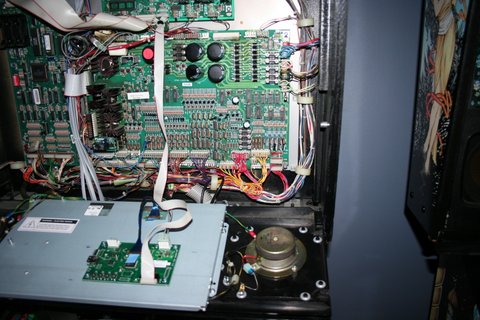
3. Choose a location for the GI OCD board. I have installed mine on the left side of the backbox.
4. Install the PCB in the location you have chosen using the provided screws.
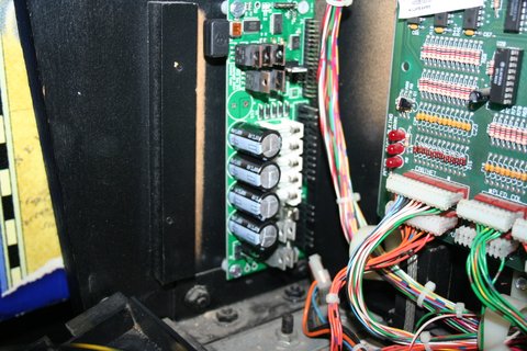
NOTE: If you don't want to make holes in your backbox by mounting the board with screws, this bracket is an option.
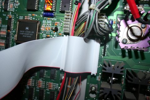
5. Remove the existing ribbon cable that is connected between J211 of the CPU board and J113 of the power driver board.
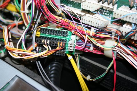
6. Connect the provided replacement ribbon cable to J211 and J113 as shown. Be VERY careful that you get the pins aligned properly.
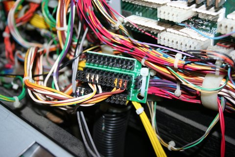
7. Connect the third connector of the replacement ribbon cable to J1 on the GI OCD board.
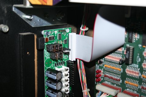
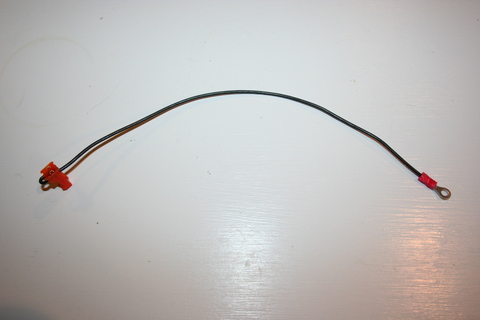
8. One end of the ground (black) cable has a single 2-pin connector. The other has a ring terminal.
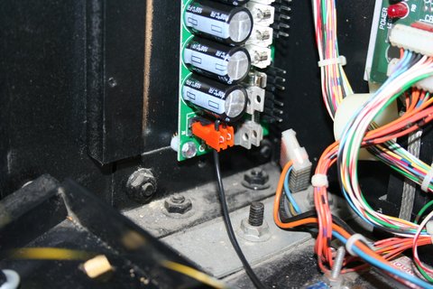
9. Connect the single 2-pin connector to J8 of the GI OCD board.
10. Remove the nut from the ground post in the lower left of the backbox.
11. Slip the ring terminal over the ground post.
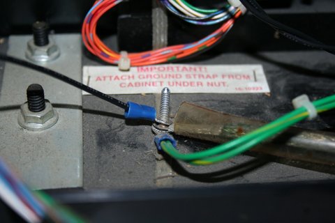
12. Replace the nut, making sure it is snug.
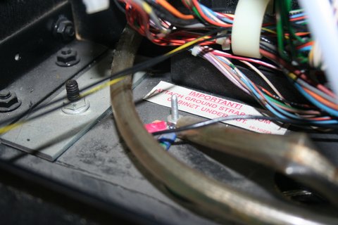
13. Secure the cable using any available cable clips.
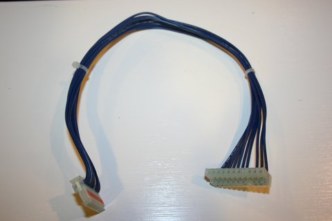
14. One end of the power input (yellow) cable has a 7-pin rectangular connector. The other end has a 9-pin square Molex connector.
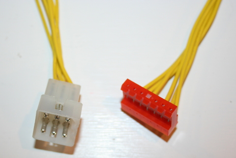
15. Connect the 7-pin connector of the power input cable to J2 of the GI OCD board.
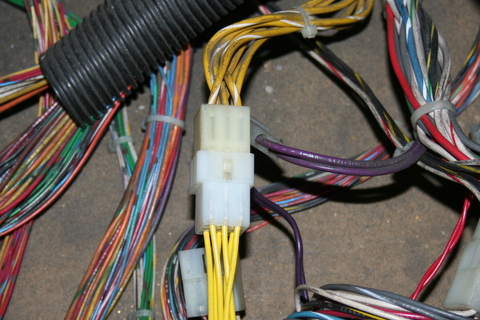
16. Drop the 9-pin connector of the power input cable through the hole in the bottom of the backbox into the cabinet.
17. Pull the playfield out to the extended position (you don’t have to lift it) to gain access to the back end of the cabinet.
18. The GI power input cable can be found in the back end of the cabinet, and it will have the same type of 9-pin Molex connector as the yellow power input cable included with the GI OCD kit. Disconnect the existing cable and connect the 9-pin connector of the new GI OCD power input cable in its place.
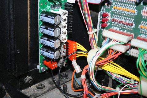
19. Secure the cable using any cable clips, plastic tubing, zip ties, etc. as necessary to prevent the cable from being pinched if the backbox is lowered at a later time.
20. You can now slide the playfield back into its normal position.
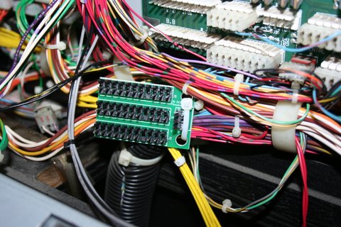
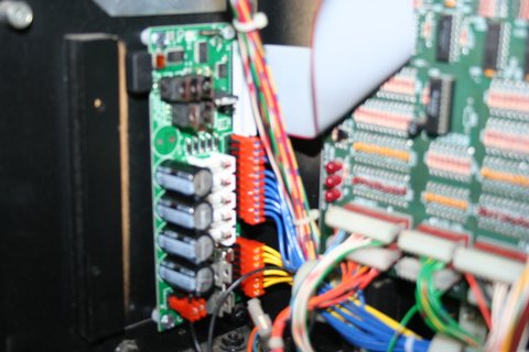
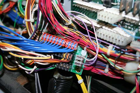
21. Secure the included breakout board near the output connectors (J119, J120, and J121) of the power driver board.
NOTE: Make sure that the exposed metal on the back of the breakout board is not laying against any other metal in the backbox. A short could occur, causing damage to either your game or the GI OCD board. SECURE IT PROPERLY!
22. Disconnect the two 11-pin connectors from J120 and J121 of the power driver board and connect them to J3 and J4 of the breakout board. It does not matter which of the two cables connects to each of the breakout board connectors.
23. Disconnect the 3-pin connector from J119 of the power driver board and connect it to J6 of the breakout board.
24. Both ends of the GI output (blue) cable have a single 11-pin connector.
25. Connect one end of the output cable to J3 of the GI OCD board.
26. Connect the other end of the output cable to J5 of the breakout board.
27. Secure the cable using any available cable clips.
28. Make sure you have replaced your GI bulbs with LEDs. If you still have incandescent bulbs installed when you turn on the power, you will blow the fuses on the GI OCD board. A few incandescents are OK, but not very many.
29. You can now turn on the machine. Verify that D11 and D10 are lit solid. D9 should blink slowly (1 second on, 1 second off).
The GI lights should work, but they will be running at default settings and can be reconfigured for better results.
If you have any "DC" bulbs in wedge sockets, they may not be lighting due to the conversion to DC. These bulbs will need to be rotated in order to work.
You are now ready for optional software installation.