
Advanced Pinball Lamp Controller
Williams WPC89 Hardware Installation
1. Turn off power to the game and wait 10 minutes.
2. Remove the translite from the game and lower the speaker panel as shown.
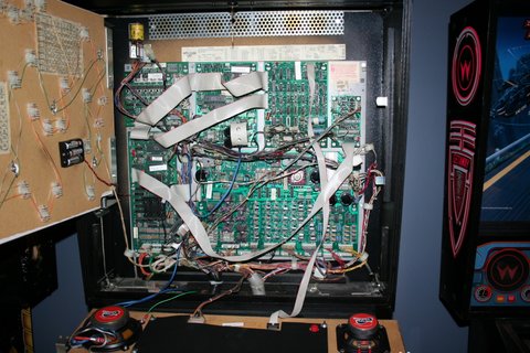
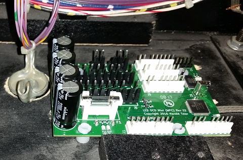
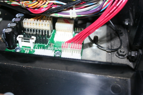
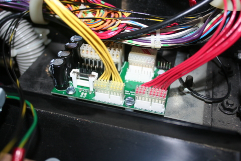
3. The LED OCD Mini board is intended to be installed in the open area at the bottom right of the backbox, below the lamp matrix connectors as shown in the picture below.
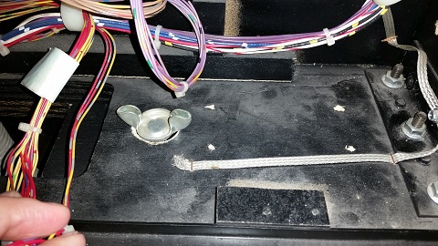
4. Use the included screws to install the PCB as shown. If you can get to all four mounting holes, that will provide the most secure mounting. The front two mounting holes are more accessible, and they should be good enough if you can't get all four screws installed.
NOTE: If you don't want to make holes in your backbox by mounting the board with screws, this bracket is an option.
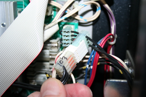
5. One end of the ground (black) cable has a single 2-pin connector. The other has two 4-pin connectors.

6. Connect the single 2-pin connector to J4 of the LED OCD board.
7. If there is a connector already connected to J103 of the WPC89 power driver board, remove it first.
8. Connect one of the remaining connectors of the provided ground cable to J103 of the WPC89 power driver board.
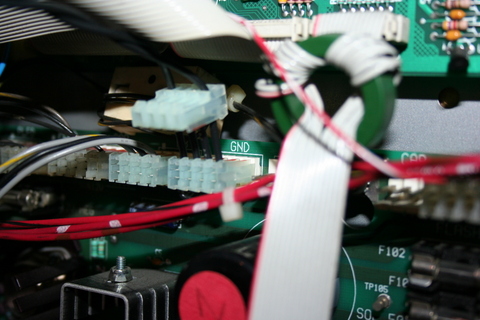
9. If you disconnected a connector from J103, insert the provided 4-pin Z-connector in the last connector of the ground cable, then attach the connector you removed from J103 to the other side of the Z-connector.
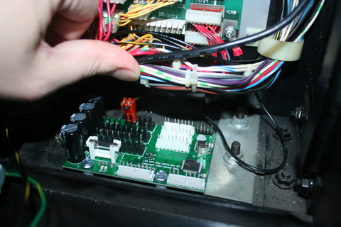
10. Secure the cable using any available cable clips.
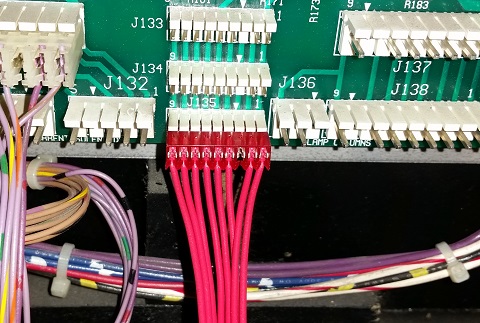
11. Disconnect all the lamp matrix row/column connectors from the power driver board, including any connectors attached to J133, J134, J135, J136, J137, or J138.
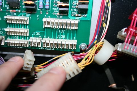
12. Connect all the lamp matrix row/column connectors you just removed to any available connector J6, J7, J8, J9, J10, or J11 of the LED OCD board.
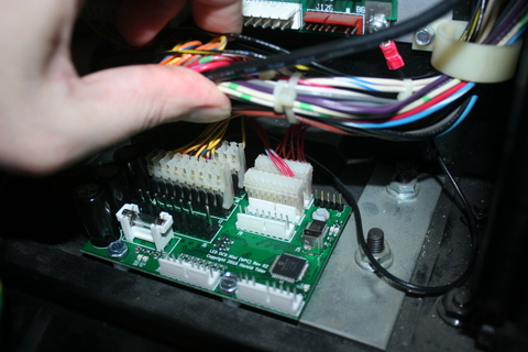
13. The row output (red) cable can be identified by the lack of a 0.156" pitch connector. Both are the smaller 0.100" pitch.
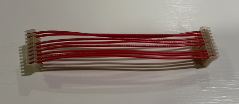
14. One end of the row output cable has a keying plug installed a pin 3. Connect this end of the cable to J133, J134, or J135 of the WPC power driver board.
15. Connect the other end (with key at pin 4) of the row output cable connector to J1 of the LED OCD board.
16. The column output (yellow) cable can be identified by the presence of a 0.156" pitch connector.
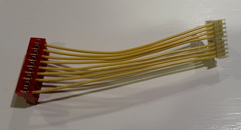
17. Connect the larger 0.156" connector to J137 or J138 of the WPC power driver board.
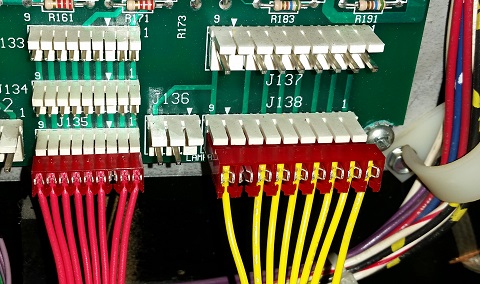
18. Connect the other end (with key at pin 5) of the column output cable connector to J2 of the LED OCD board.
19. Make sure you have replaced your controlled bulbs with LEDs. If you still have incandescent bulbs installed when you turn on the power, you will blow the fuse on the LED OCD board. A few incandescents are OK, but not a game full of them. If you really need to use a bunch of incandescent bulbs, you can increase the fuse to a 4A to make it work like the original LED OCD, but this will result in the LED OCD being in danger of damage if a short occurs.
20. You can now turn on the machine. Verify that D11 and D10 are lit solid. D9 should blink slowly (1 second on, 1 second off).
The insert lights should work, but they will be running at default settings and should be reconfigured for best results.
PC Software and USB Cable
You have the option of using PC Software and a mini-USB cable to change settings on the board.
1. Turn off power to the game and wait 10 minutes.
2. Connect the a mini-USB cable to the mini-USB connector J5 on the LED OCD board.
You are now ready for software installation.