
Advanced Pinball Lamp Controller
Williams WPC89 Hardware Installation
1. Turn off power to the game and wait 10 minutes.
2. Remove the translite from the game and lower the speaker panel as shown.
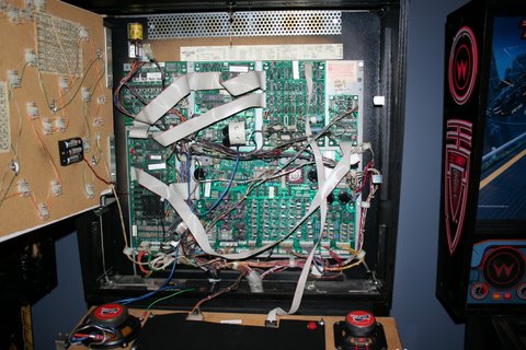
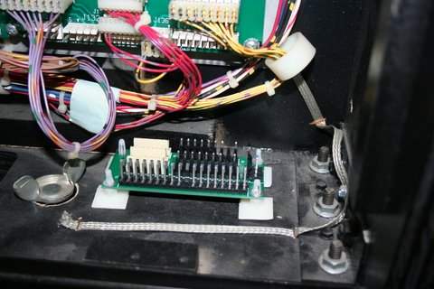
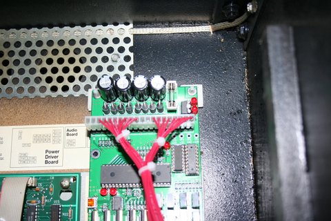
3. Choose a location for the LED OCD board. I recommend the open area as shown in the picture below.
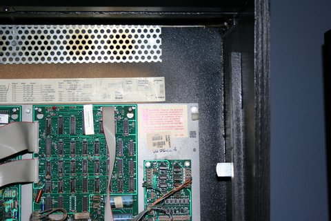
4. Insert the four provided standoffs in the four corner holes in the PCB.
5. Clean the area where the standoffs will be stuck using isopropyl alcohol.
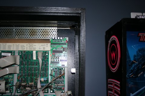
6. Remove the backing from the adhesive pads on the standoffs and place the PCB in the location you have chosen. Make sure to leave enough room on the left of the LED OCD board for the USB cable.
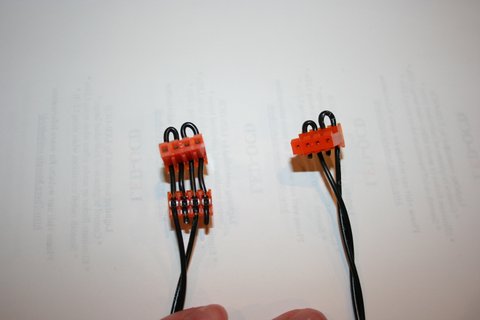
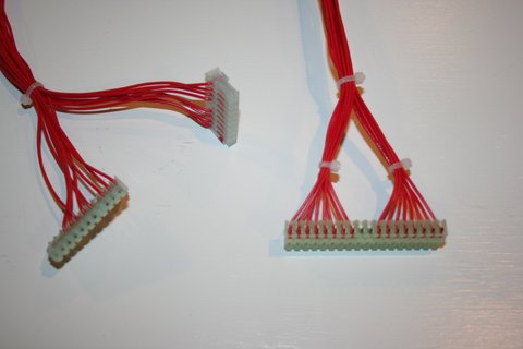
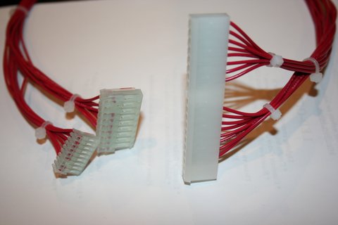
7. One end of the ground cable has a single 4-pin connector. The other has two 4-pin connectors.
8. Connect the single 4-pin connector to J4 of the LED OCD board.
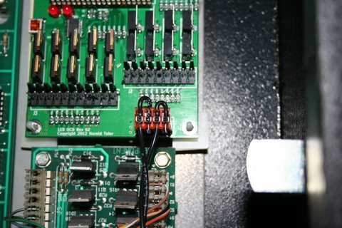
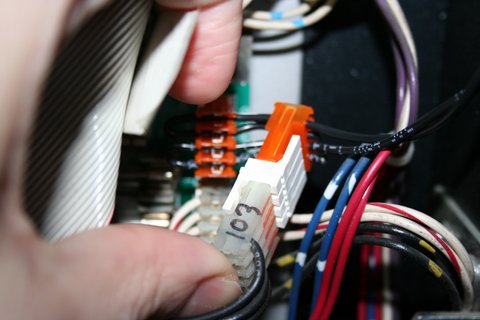
9. If there is a connector already connected to J103 of the WPC89 power driver board, remove it first.
10. Connect one of the remaining connectors of the provided ground cable to J103 of the WPC89 power driver board.
11. If you disconnected a connector from J103, insert the provided 4-pin Z-connector in the last connector of the ground cable, then attach the connector you removed from J103 to the other side of the Z-connector.
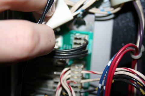
12. Secure the cable using any available cable clips.
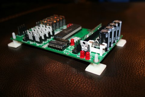
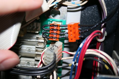
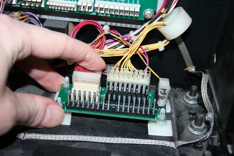
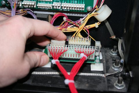
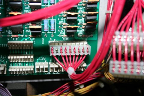
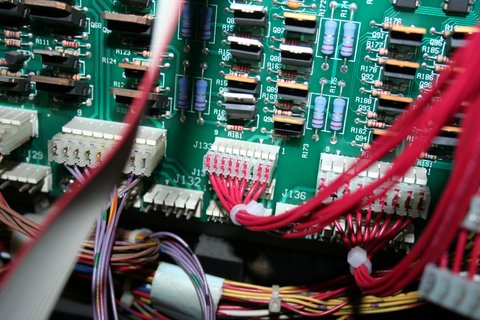
13. Like you did with the main PCB, choose the location for the small breakout PCB and install it. It is shown here with the adhesive standoffs, but you will probably be using screw standoffs. It needs to be close enough to the lamp matrix connectors on the playfield harness that they can be moved from the power driver board.
14. Disconnect all the lamp matrix row/column connectors from the power driver board, including any connectors attached to J133, J134, J135, J136, J137, or J138.
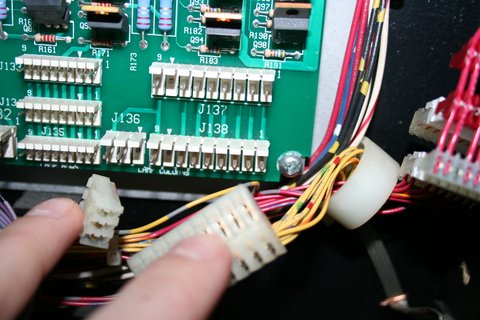
15. Connect all the lamp matrix row/column connectors you just removed to any available connector J1, J2, J3, J4, J5, or J6 of the LED OCD breakout board.
16. The row/column output cable can be identified by the lack of a 0.100" pitch connector. All three are the larger 0.156" pitch. 18-pin, 9-pin, and either 11-pin or 9-pin. The newer ones will have two 9-pin connectors rather than one 9-pin and one 11-pin.
17. Connect the 18-pin connector to J7 of the LED OCD breakout board.
18. Connect the 11-pin/9-pin (with key at pin 4) connector to J3 of the LED OCD board. If your cable has the 9-pin connector, it will be flush with the pin 1 end (right) of J3 and pins 10 and 11 will be exposed.
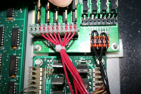
19. Connect the 9-pin (with key at pin 5) connector to J2 of the LED OCD board. It is keyed, and is the only 9-pin connector that will properly fit J2. Make sure the side of the connector with the ramp is pressing against the "springy" side of J2. This actually goes for all of the connectors, but this one can be flipped without noticing it since the key is in the center location. The wires should exit the connector over the top of J4.
20. Secure the cable using any available cable clips.
21. The remaining cable is the row/column input cable, and can be identified by the 9-pin 0.1" pitch (smaller than all the others) connector. There is also a 9-pin 0.156" pitch connector and either an 18-pin or 20-pin connector on this cable. The newer ones will have the 18-pin connector.
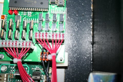
22. Connect the 18-pin (or 20-pin) connector to J1 on the LED OCD board. If this is an 18-pin connector, pins 19 and 20 of J1 will be exposed. The connectors are keyed to prevent improper installation.
23. Connect the 9-pin 0.156" connector to J137 of the WPC power driver board.
24. Connect the 9-pin 0.100" connector to J133 of the WPC power driver board.
25. Secure the cable using any available cable clips.
26. You can now turn on the machine. Verify that D11 and D10 are lit solid. D9 should blink slowly (1 second on, 1 second off).
The insert lights should work, but they will be running at default settings and should be reconfigured for best results.
PC Software and USB Cable
You have the option of using PC Software and a mini-USB cable to change settings on the board.
1. Turn off power to the game and wait 10 minutes.
2. Connect the a mini-USB cable to the mini-USB connector J5 on the LED OCD board.
You are now ready for software installation.