
Advanced Pinball Lamp Controller
GI OCD Williams WPC95 Hardware Installation
1. Turn off power to the game and wait 10 minutes.
2. Remove the translite from the game and lower the speaker panel as shown.
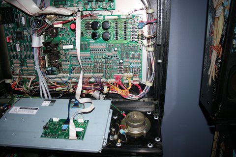
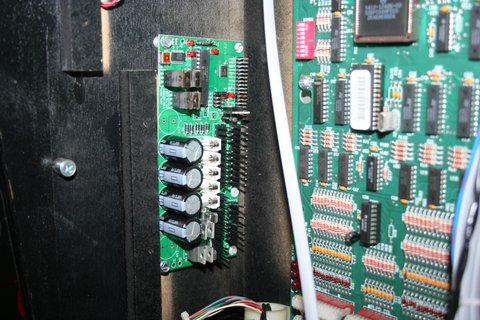
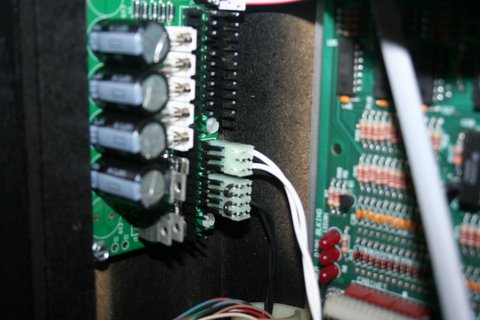
3. Choose a location for the GI OCD board. I have installed mine on the left side of the backbox.
4. Install the PCB in the location you have chosen using the provided screws.
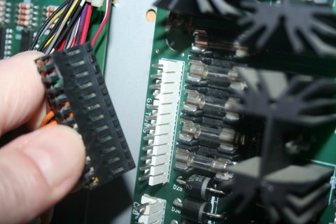
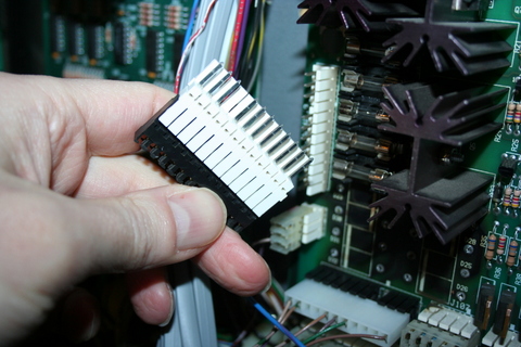
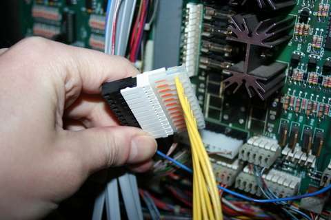
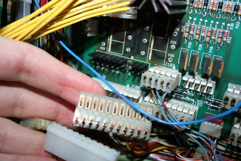
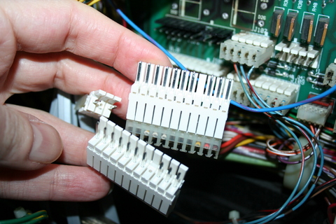
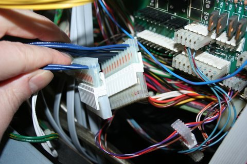
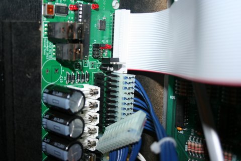
5. Remove the existing ribbon cable that is connected between J211 of the CPU board and J102 of the power driver board.
6. Connect the provided replacement ribbon cable to J211 and J102 as shown. Be VERY careful that you get the pins aligned properly.
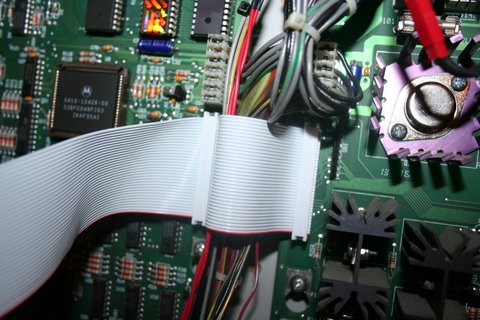
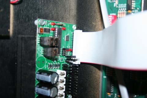
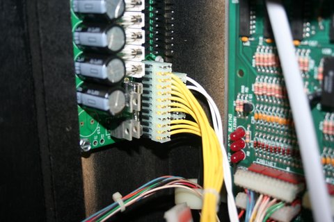
7. Connect the third connector of the replacement ribbon cable to J1 on the GI OCD board.
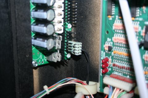
8. One end of the ground (black) cable has a single 4-pin connector. The other has a ring terminal.
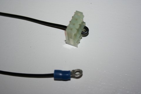
9. Connect the single 4-pin connector to J8 of the GI OCD board.
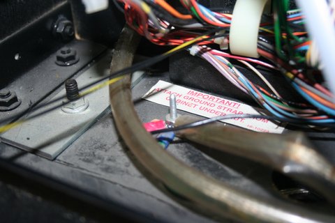
10. Remove the nut from the ground post in the lower left of the backbox.
11. Slip the ring terminal over the ground post.
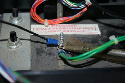
12. Replace the nut, making sure it is snug.
13. Secure the cable using any available cable clips.
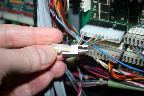
14. Disconnect the 3-pin coin door lamp cable from J104 of the power driver board.
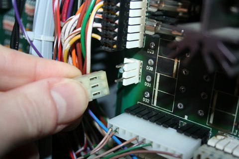
15. Insert the provided 3-pin Z-connector into the connector you just removed.
16. Both ends of the coin door lamp extension (white) cable have a single 3-pin connector.
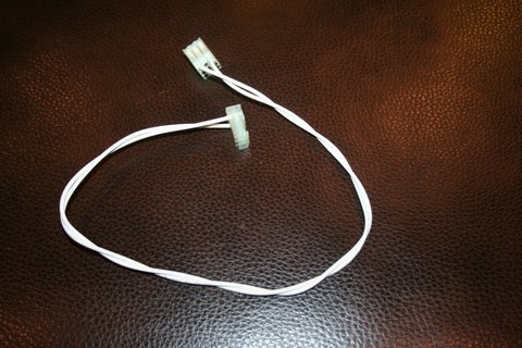
17. Attach the other side of the 3-pin Z-connector to either 3-pin connector on the provided extension cable.
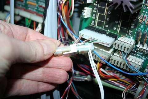
18. Attach the other end of the extension cable to J5 of the GI OCD board.
19. Secure the cable using any available cable clips.
NOTE: Make sure that none of the connectors are laying against any of the boards. The IDC connectors have exposed metal on their backs that could short against other things in the backbox. SECURE THEM PROPERLY!
20. Disconnect the GI power supply cable from J103 of the power driver board.
21. Insert the provided 12-pin Z-connector into the connector you just removed.
22. Both ends of the power input extension (yellow) cable have a single 12-pin connector.
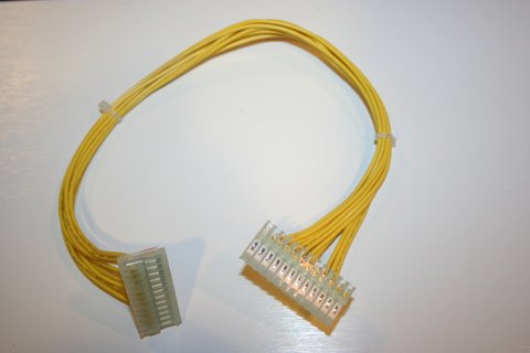
23. Attach the other side of the 12-pin Z-connector to either 12-pin connector on the provided extension cable.
24. Attach the other end of the power cable to J2 of the GI OCD board.
25. Secure the cable using any available cable clips.
NOTE: Make sure that none of the connectors are laying against any of the boards. The IDC connectors have exposed metal on their backs that could short against other things in the backbox. SECURE THEM PROPERLY!
26. Disconnect the two 11-pin GI lamp cables from J105 and J106 of the power driver board.
27. Insert the provided two 11-pin Z-connectors into the connectors you just removed.
28. Both ends of the GI output extension (blue) cables have a single 11-pin connector. Two of these cables are provided.
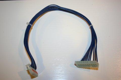
29. Attach the remaining side of each of the 11-pin Z-connectors to either of the 11-pin connectors on each of the provided extension cables.
30. Attach the other end of the output cables to J3 and J4 of the GI OCD board. It doesn't matter which cable connects to which connector.
31. Secure the cables using any available cable clips.
NOTE: Make sure that none of the connectors are laying against any of the boards. The IDC connectors have exposed metal on their backs that could short against other things in the backbox. SECURE THEM PROPERLY!
32. Make sure you have replaced your GI bulbs with LEDs. If you still have incandescent bulbs installed when you turn on the power, you will blow the fuses on the GI OCD board. A few incandescnets are OK, but not very many.
33. You can now turn on the machine. Verify that D11 and D10 are lit solid. D9 should blink slowly (1 second on, 1 second off).
The GI lights should work, but they will be running at default settings and should be reconfigured for best results.
If you have any "DC" bulbs in wedge sockets, they may not be lighting due to the conversion to DC. These bulbs will need to be rotated in order to work.
You are now ready for software installation.