Advanced Pinball Lamp Controller
GI OCD Usage Instructions
1. Start the GI OCD application.
NOTE: If you see a message saying that FTD2XX.dll cannot be loaded, it normally means the drivers have not been properly installed. Connect the USB cable between the PC and GI OCD board, power on the game, and complete driver installation before running the configuration program.
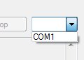
2. Pull down the COM port selection menu and make note of what ports are in the list. These are the COM ports already active on your system.
3. Connect the USB cable from the GI OCD board to your PC.
4. Turn on the game.
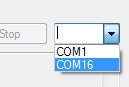
5. Pull down the COM port selection menu again. There should be one new COM port displayed. This is the port that is used to communicate with the GI OCD board. Select it.
6. Press the Connect button. You should see the message "Deteced GI OCD Firmware vX".
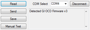
7. Press the Read button. The current settings will be read from the GI OCD and displayed.
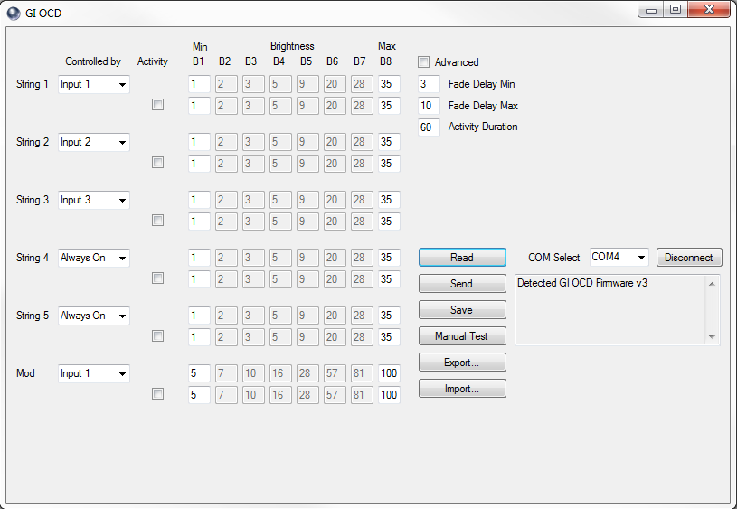
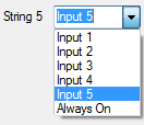
8. There are six drop down menus on the left side of the window. The first five are used to select which input source is used to control each of the five GI strings. The sixth menu is for an optional feature to control an external mod and can be ignored. Selecting "Input x" from any of these menus causes it to be controlled by the corresponding output from the pinball machine. Selecting "Always On" from any of these menus causes that string to remain at B8 all the time. These can be mixed and matched any way you please, but there are really only a few combinations that make sense.
Input 1, Input 2, Input 3, Input 4, Input 5 makes it work like a WPC89 game where all five strings are controlled by the pinball machine. If you use this for a WPC95 game, however, strings 4 and 5 will remain off.
Input 1, Input 2, Input 3, Always On, Always On makes it work like a WPC95 game where three strings are controlled by the pinball machine and two strings remain on all the time. If you use this for a WPC89 game, however, strings 4 and 5 will remain on, instead of being controlled like they should.
Input 1, Input 2, Input 3, Input 1, Input 2 (or something similar) is useful to make WPC95 games more active. This allows strings 4 and 5 (normally the backbox) to be controlled even though there is not anything programmed into the pinball machine to control them. One example where this is useful is AFM. During Strobe Multiball, the machine turns off the playfield GI, and this setting will also turn off the backbox GI, making it completely dark.
9. Each string of GI has two sets of eight brightness values associated with it. The top row is the "normal" brightness mapping. These values are the duty cycles that correspond to each of the eight brightness levels as controlled by the pinball machine. The higher these values are set, the brighter the GI bulbs in that string will appear. By default, only the dimmest value (B1) and the brightest value (B8) will be able to be changed. The intermediate values will automatically change based on these in order to create a nice ramp. If you want to control the intermediate values yourself, you can check the "Advanced" checkbox, and they will become available for changes.
NOTE: Since the rectified voltage is over 9V DC, setting the brightness to 100% duty will be overdriving the LEDs. This can lead to the LEDs failing prematurely. The exact value that is "safe" depends on the design of the LEDs that are in use, and there are too many variables for us to be able to tell you what that maximum is for your bulbs. We recommend that 40% is the highest duty you use, but the software currently does not limit this. You will see a colored backgound as a warning if you set the duty higher than the recommended value.
If you set a brightness value too low, it can cause the LEDs to flicker. The level at which they will flicker depends on the exact bulbs being used.
The second row is the "active" brightness mapping. It is only used if the "Active" checkbox for that string is checked and only if the machine is currently active.
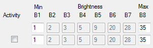
10. What does "currently active" mean? GI OCD monitors solenoid activity, and uses that to determine is a game if being played. Once a solenoid fires, GI OCD considers the game active and will use the "active" brightness mapping if the checkbox is checked. If the checkbox is not checked, it will continue to use the "normal" mapping.
It also starts a timer that is used to determine when the game is no longer active. The duration of this timer can be set by changing the value in the "Activity Duration" textbox.

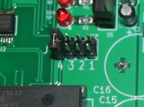
Finally, only one of the solenoid strobe signals can be monitored at a time. This is selectable using a jumper on J7 of the GI OCD board. It is recommeded that you use the signal that includes the trough eject solenoid, but which of the four signals controls the trough eject varies from game to game. By changing the location of the jumper shown, then causing the trough eject solenoid to fire, you can find which one to use. ALWAYS INSTALL THE JUMPER IN A VERTICAL ORIENTATION AS SHOWN. DO NOT PLACE MORE THAN ONE JUMPER ON J7.
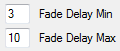
11. In order to make changes in brightness more pleasing, GI OCD gradually ramps between brightness values. The speed of this can be controlled by the "Fade Delay Min" and "Fade Delay Max" settings. The minimum value is used when brightness is changing quickly, and the maximum value is used when the brightness changes slowly. The default minimum value is "3", and we feel this gives the best results, however you are free to change it. The maximum value is more game dependent, so trying different values is encouraged.
12. Before any of these changes are sent to the GI OCD board, you must click the "Send" button.
13. Once all the lamps look like you want, be sure to click the Save button to retain the settings once the machine is powered off.
14. The Export and Import buttons can optionally be used to save and restore settings using XML files on your PC.
Manual Test
In order to have more control of the lamps while choosing brightness values, it can be useful to be able to force bulbs to remain static. This is what the manual test allows you to do.
1. Click the "Manual Test" button. Additional controls will appear on the GI OCD configuration window, and all the pinball machine lamps will turn off.
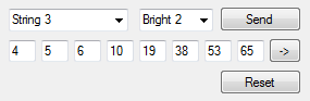
2. The first row of new controls include two dropdown menus that can be used to force a string of lamps to change to and remain at a brightness level. Select a string from the first menu and a level from the second menu, then click Send.
3. The second row of new controls are used to set the brightness percentage of each of the eight brightness levels, just as in the standard controls. Enter the percentages you want to test, then click the "->" button.
4. Repeat steps 2 and 3 to change lamps as you see fit. A couple of very useful tests are to set a string to brightness level 1, another to level 8, and try different percentages to figure out what maximum and minimum values look good to you.
5. Finally, the Reset button can be used to return all the strings to brightness zero (off).
6. When you are finished with the advanced controls, click "Game Control", and the manual test controls will be hidden once again. Control of all lamps will also be returned to the pinball machine.
Using the Auxillary Mod Control
NOTE: This feature is not intended as a core feature of GI OCD. It is more of a "freebie" that I added based upon a request. I am willing to help with it, but you will be expected to pull most of the load if you are using it.
1. Populate Q10 with an IRL540 transistor.
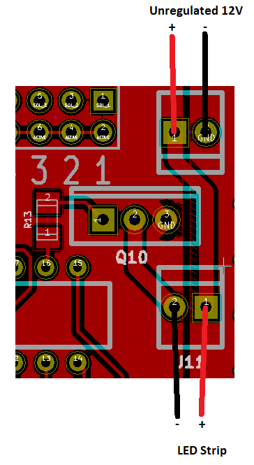
2. Connect your power input to J10. Pin 1 is positive and is indicated by the square pad on the PCB. Pin 2 is tied to the pinball machine ground. If you want to use a connector for J10 (and J11), I designed it for a Molex 22-23-2021.
You can also "steal" power from the 9V supply already on the GI OCD board as long as your mod is OK with ~8-10V DC unregulated and doesn't pull too much current. How much is too much? That depends on what load your GI lighting is already pulling, but a safe value would be ~500mA. I designed to 10A total for the 9V source, but it has not been tested that high. There is a fuse on the input, but DO NOT count on it to do your work for you. You will need to do your own research if you attempt this.
3. Connect your topper (or lighting strip or other mod) to J11. Again, pin 1 is positive and indicated by the square pad.
4. Control your mod through the GI OCD software using the same method as all the other standard GI strings.
For example, see the image below.